Building the Inspect measurement engine
Not too long ago I had the opportunity to construct a measurement system inside of Inspect that depicts and calculates the distances between two layers. In-between each layer, a line is drawn with a label that displays the distance. Supporting lines are added to the nearest edges of the hovered layer to help give the user an idea where the measurement lines reach.
In this article, I’ll explain some of my ideas and how I managed to take a fairly complex problem, break it down, and deliver something of value to an end user. I hope by you reading through this article; you’ll have a better understanding of how to dissect a problem you may be encountering. I know when I was handed the ticket to implement this functionality, it was intimidating.
After sitting down and thinking about how to approach this problem, I concluded that a higher-order component would handle the business logic and then pass the required data down to a stateless component. I came to this conclusion by thinking about how I could break a single piece of functionality down into independent pieces. If you think about it, there are really only two main pieces: the logic, and then the view.
Breaking down the task at hand
By breaking down a task into several smaller tickets, you immediately reap in all these benefits: You can give better estimates on how long a single ticket takes since the scope is much smaller. You feel more productive shipping multiple smaller tickets in a single sprint versus a giant one.
At InVision, our team uses JIRA to manage bugs, new features and everything that needs to be tracked or accounted for. By separating the view from the business logic, not only can I now split a single ticket into two smaller tickets, but was able to go one step further. I created a ticket to deal with outlining what values should be passed from the HOC to the child component. Three tickets have been created from what was originally one and can now be tracked and dealt with independently.
The outline
Every problem gives you better results if you sit down and think about how to approach it before execution. This step is a great time to bounce ideas off your coworkers to see if they agree with your suggested approach or have a way to make it even better. Without this first step, I may have over-engineered or made this much more complicated than it needed to be.
Looking at the design mockups from the designer, the first thing I see I can see that I need to draw a rectangle around both the selected and a hovered layer. Both of these values exist within the global state so that I can pass these properties from a parent component and down to the view without additional data transformation.
type Props = {
  selectedLayer?: Layer,
  hoveredLayer?: Layer
}
The next obvious thing that needs to be pass down the view component is all the measurements. There can be up to four separate measurements rendered at a single time, so the clear choice here is to use an array of objects. Now I need to figure out the shape of each measurement.
type Measurements Measurement[]
Each measurement must have a direction which is either top, right, bottom or left. Based on this information alone, I’ll use this to draw a specific side of the border. The first property I’ll add to the measurement object is the direction. Next, I need a start and end position for each measurement. It contains an an x, y coordinate with either a width or height, depending on whether it’s vertical or horizontal.
type Position = {
  top: number,
  left: number,
  width?: number,
  height?: number
}

type Measurement = {
  direction: number,
  label: Label,
  position: Position
}
The last item that exists within each measurement is the label to display the distance. Whenever the measurement is inside the artboard, the label is positioned in the middle of the measurement line. To position the label, I’ll need an x and y coordinate.
type Point = {
  x: number,
  y: number
}

type Label {
  point: Point,
  value: string
}
Side note: the outline was created using Flow type definitions to help validate that the data types passed down the view is correct. Both Flow and Typescrpt are excellent choices if you want the type safety and reassurance that the right data is being passed around in your application. You end up with fewer bugs and feel way more confident in your codebase.
Here is the entire structure:
type Point = {
  x: number,
  y: number
}

type Label {
  point: Point,
  value: string
}

type Position {
  top: number,
  left: number,
  width?: number,
  height?: number
}

type Measurement {
  direction: number
  label: Label,
  position: Position
}

type Measurements Measurement[]
The business logic
The higher-order component contains all our business logic which is the heart of this functionality. Its job is to take the hover and selected layer and transform that data into the structure defined in the outline.
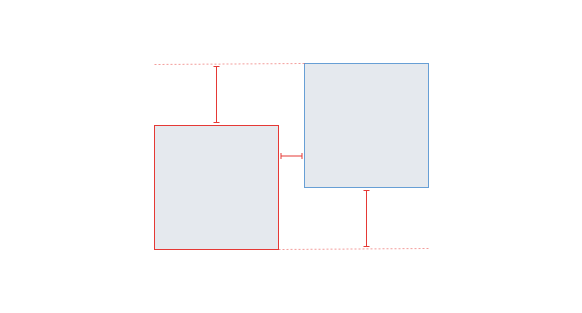
The key thing to determine was where in relation one layer is to another, and then calculate the distance between the closest sides. These values are typically what a developer is most interested in to set the position, margin or padding of an element. There are two main paths which the logic can follow, either the selected and hover layer are overlapping each other, or they are not.
Two layers which intersect Two layers in relation to eachother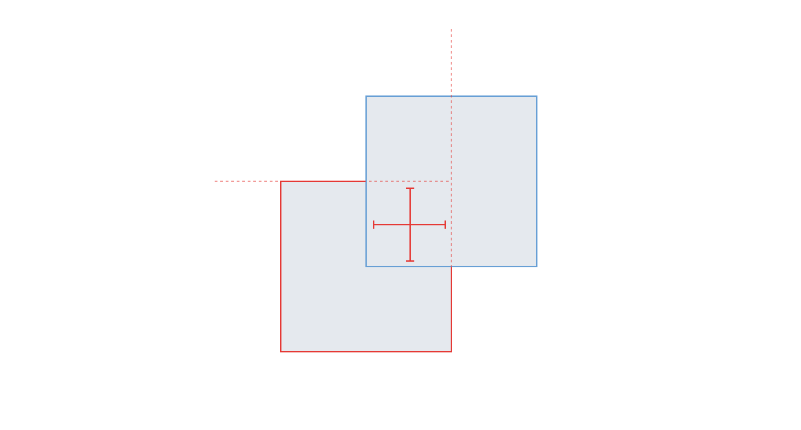
Before I dive into both paths, there are a couple of checks which need to happen. First, I need to determine if only selected layers are passed in or both the selected and hovered layers. If only the selected layer is passed in, I use the properties from the artboard and create the hovered layer manually. This allows me to calculate the position of the layer in relation to the artboard itself without adding additional checks whether the layer is an artboard or not.
The properties I worry about for each layer are the width, height, and x, y coordinates. Here is a simplification of the layer shape, but it gives you an idea of some basic properties it contains.
type Layer = {
  id: number,
  width: number,
  height: number,
  x: number,
  y: number
}
To figure out which path I can take, I started by determining if the layers are overlapping by both the x and y-axis. If both of these return true, I know which path I’ll need to follow.
// Determine if the x axis plus width overlap
const xIntersects = (layer1: Layer, layer2: Layer): boolean =>
  Math.max(
    0,
    Math.min(layer1.x + layer1.width, layer2.x + layer2.width) -
      Math.max(layer1.x, layer2.x)
  ) > 0

// Determine if the y axis plus height overlap
const yIntersects = (layer1: Layer, layer2: Layer): boolean =>
  Math.max(
    0,
    Math.min(layer1.y + layer1.height, layer2.y + layer2.height) -
      Math.max(layer1.y, layer2.y)
  ) > 0

// Determine if both x and y-axis plus width and height overlap
const overlaps = (layer1: Layer, layer2: Layer): boolean =>
  xIntersects(layer1, layer2) && yIntersects(layer1, layer2)
The next piece of information shared among all different paths is the direction. The way I’ve decided to calculate the direction is to think of a 3x3 grid which starts at zero and increments in a clockwise fashion. Starting from the middle, eight, I need to determine where the second layer is in relation to the first one.
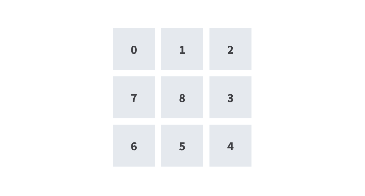
Each direction numbered from one to eight in relation to the center
const BOTTOM = 5
const BOTTOM_LEFT = 6
const BOTTOM_RIGHT = 4
const CENTER = 8
const LEFT = 7
const RIGHT = 3
const TOP = 1
const TOP_LEFT = 0
const TOP_RIGHT = 2

const DIRECTIONS = [
  TOP,
  TOP_RIGHT,
  RIGHT,
  BOTTOM_RIGHT,
  BOTTOM,
  BOTTOM_LEFT,
  LEFT,
  TOP_LEFT
]
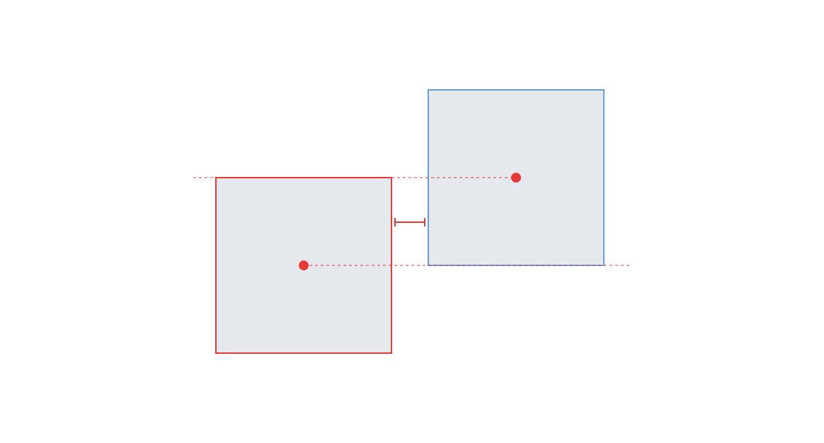
Now that I’ve set up these variables I can work on the math portion to determine the cardinal direction between the two layers. This can be accomplished by determining the absolute center of both layers and then calculating the angle between the two.
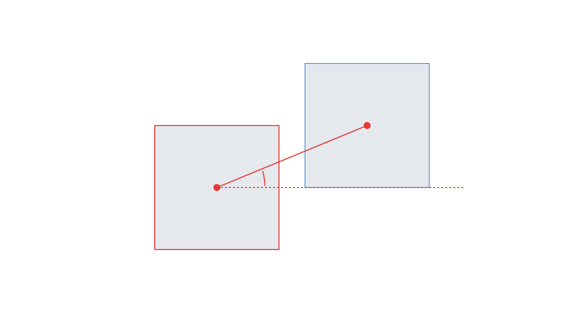
Two shapes with their centers marked and a line drawn between the two to demonstrate the angle
const getDirection = (layer1: Layer, layer2: Layer): number => {
  // Get the x and y center of each layer
  const layer1Center: Point = getCenter(layer1)
  const layer2Center: Point = getCenter(layer2)

  // Check if this coordinate is dead center with other.
  if (layer1Center.x === layer2Center.x && layer1Center.y === layer2Center.y) {
    return CENTER
  }
  const angle = getAngle(layer2Center, layer1Center)
  return angleToDirection(angle)
}

// Convert the angle to a direction
const angleToDirection = (angle: number): number => {
  const directionCount = DIRECTIONS.length
  return DIRECTIONS[
    Math.floor(angle / (360 / directionCount) + 0.5) % directionCount
  ]
}

// Calculate the angle between the center of two points
const getAngle = (point1: Point, point2: Point): number => {
  const angle =
    (Math.atan2(point2.y - point1.y, point2.x - point1.x) * 180) / Math.PI - 90
  return angle < 0 ? 360 + angle : angle
}

// Get the absolute center point of a layer
const getCenter = (layer: Layer): Point => ({
  x: layer.x + layer.width / 2,
  y: layer.y + layer.height / 2
})
Now that the logic is out of the way I can carry on with actually using it.
const layerOverlapsLayer = overlaps(selected, highlighted)
const cardinal = getDirection(selected, highlighted)
Layers which overlap
Overlapping layers is the easier option of the two paths to calculate. The first step I chose to do here was to calculate all four sides of the selected layer and build up each measurement. This achieved by calculating the minimum and maximum values for each side, and then subtracting the same side of the opposite layer.
const top = Math.abs(layer1.y - layer2.y)
const right = Math.abs(layer1.x + layer1.width - (layer2.x + layer2.width))
const bottom = Math.abs(layer1.y + layer1.height - (layer2.y + layer2.height))
const left = Math.abs(layer1.x - layer1.x)
Performing the above calculations gives us the difference for each side which we can use to display the label width and height of the measurement lines.
Next, I need to determine the intersection point of all sides. The function below determines the central intersection point between two layers. This function is essential to center the line vertically or horizontally between two facing sides.
Two layers which intersect
const intersection = (layer1: Layer, layer2: Layer): Point => {
  const xMax = Math.max(layer1.x, layer2.x)
  const yMax = Math.max(layer1.y, layer2.y)

  return {
    x:
      xMax +
      Math.max(
        0,
        Math.min(layer1.x + layer1.width, layer2.x + layer2.width) - xMax
      ) /
        2,
    y:
      yMax +
      Math.max(
        0,
        Math.min(layer1.y + layer1.height, layer2.y + layer2.height) - yMax
      ) /
        2
  }
}
Now that we have the intersection and offsets, we can use this information to can start building out the measurements. I decided to calculate all four sides and then only return what is required.
const yMin = Math.min(layer1.y, layer2.y)
const xMin = Math.min(layer1.x, layer2.x)
const yHeightMin = Math.min(layer1.y + layer1.height, layer2.y + layer2.height)
const yHeightMax = Math.max(layer1.y + layer1.height, layer2.y + layer2.height)
const xWidthMin = Math.min(layer1.x + layer1.width, layer2.x + layer2.width)
const xWidthMax = Math.max(layer1.x + layer1.width, layer2.x + layer2.width)
const intersects = intersection(layer1, layer2)

const topMeasurement: Measurement = {
  direction: TOP,
  position: {
    top: yMin,
    left: intersects.x,
    height: top
  },
  label: {
    point: {
      y: yMin + top / 2,
      x: intersects.x
    }
  }
}

const rightMeasurement: Measurement = {
  direction: RIGHT,
  position: {
    top: intersects.y,
    left: xWidthMin,
    width: right
  },
  label: {
    point: {
      y: intersects.y,
      x: xWidthMax - right / 2
    },
    value: right
  }
}

const bottomMeasurement: Measurement = {
  direction: BOTTOM,
  position: {
    top: yHeightMin,
    left: intersects.x,
    height: bottom
  },
  label: {
    point: {
      y: yHeightMin + bottom / 2,
      x: intersects.x
    },
    value: bottom
  }
}

const leftMeasurement: Measurement = {
  direction: LEFT,
  position: {
    top: intersects.y,
    left: xMin,
    width: left
  },
  label: {
    point: {
      y: intersects.y,
      x: xMin + left / 2
    },
    value: left
  }
}
Now that all the measurements values are calculated, I can work on the returned value. When the selected layer is perfectly centred with the hover layer, all four measurements will be returned since I cannot successfully determine which side the end user wants to see.
if (cardinal === CENTER) {
  return [topMeasurement, rightMeasurement, bottomMeasurement, leftMeasurement]
}
When the two layers are not concentric, all sides which extend beyond the selected layer need to be omitted from the result.
const measurements: Measurements = []

// Top
if (layer1.y < layer2.y) {
  measurements.push(topMeasurement)
}

// Right
if (layer1.x + layer1.width > layer2.x + layer2.width) {
  measurements.push(rightMeasurement)
}

// Bottom
if (layer1.y + layer1.height > layer2.y + layer2.height) {
  measurements.push(bottomMeasurement)
}

// Left
if (layer1.x < layer2.x) {
  measurements.push(leftMeasurement)
}

return measurements
Non-overlapping layers
Non-overlapping layers are when two layers do not intersect in any way. They are a bit more complicated to calculate since there are many more variables to consider when comparing it to two overlapping layers.
My thought of approaching this is to create a switch statement based on the
cardinal direction and calculate each side independently. There would be a total
of eight cases to account for, top left, top, top right, right, bottom right,
bottom, bottom left and left. Since these layers never overlap in any way, I’ll
never have to worry about calculating the CENTER.
const distance = (cardinal, layer1, layer2) => {
  switch (cardinal) {
    case TOP_LEFT:
      ...
      break
    case TOP:
      ...
      break
    case TOP_RIGHT:
      ...
      break
    case RIGHT:
      ...
      break
    case BOTTOM_RIGHT:
      ...
      break
    case BOTTOM:
      ...
      break
    case BOTTOM_LEFT:
      ...
      break
    case LEFT:
      ...
      break
  }
}
Each measurement would be calculated independently and similarly as the
overlapping layers. On paper, this seemed to work well and would account for
most cases I would expect. After some initial testing, I noticed
that some cases did not display what I had expected to see. Whenever a layer is
in-between two directions, lets say TOP and TOP_LEFT, it would fall into the
TOP_LEFT case.
Actual result Expected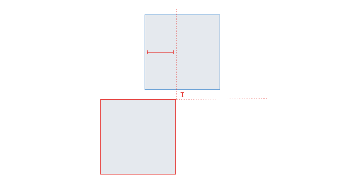
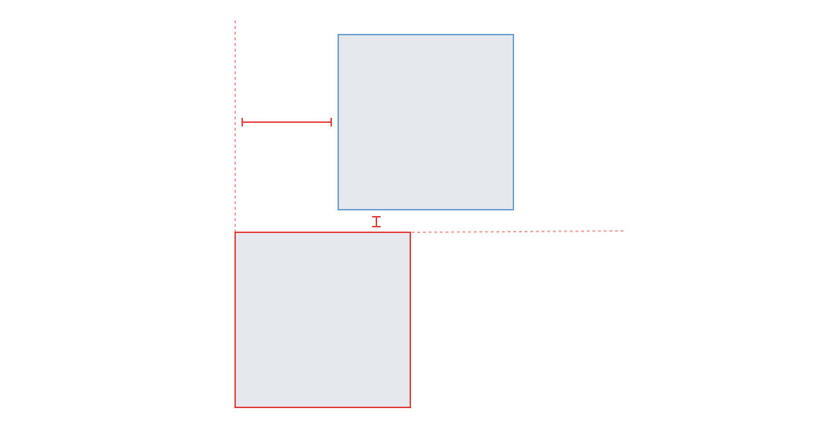
I added an if statement to all four corners (sides 0, 2, 4, and 6) to check if
either the hover layer overlaps the selected layer or the hover layer extends
past the selected layer. Whenever this was true, I changed the cardinal
direction to either TOP, RIGHT, BOTTOM or LEFT, depending on the
overlap, and returned the distance function.
const xWidth = layer1.x + layer1.width
const yHeight = layer1.y + layer1.height
const x2Width = layer2.x + layer2.width
const y2Height = layer2.y + layer2.height

const overlapsMiddleY = layer2.y < layer1.y && y2Height > yHeight
const overlapsMiddleX = layer2.x < layer1.x && x2Width > xWidth

if (overlapsMiddleX || layer2.x >= layer1.x || x2Width > layer1.x) {
  return distance(TOP, layer1, layer2)
} else if (overlapsMiddleY || layer2.y >= layer1.y) {
  return distance(LEFT, layer1, l)
}
Putting it all together
So far I have thrown example after example at you but haven’t given you an idea how it all fits together. In the next example, I put together a super stripped down version, so you have an idea of how this all works.
// composites/measurementHandler.js
type Props = {
  artboard: Artboard,
  hoveredLayer?: Layer,
  selectedLayer: Layer
}

export default (ComposedComponent: React.ComponentType<*>) =>
  class SelectionMeasurementHandler extends React.Component<Props, void> {
    render() {
      let { selectedLayer, hoveredLayer, artboard }: Props = this.props

      // If there is only a selected layer and no hovered layer, use the artboard
      // measurements instead so you can see where the layer is in relation to
      // the artboard.
      if (!hoveredLayer) {
        const { width, height, id } = artboard
        hoveredLayer = {
          x: 0,
          y: 0,
          id,
          width,
          height
        }
      }

      // Is the selected layer inside the hovered layer or is the hovered layer
      // inside the selected layer?
       const inside = contains(selectedLayer, hoveredLayer) ||
          contains(hoveredLayer, selectedLayer)

      // Does the selected layer overlap the hoveredLayer in any way
      const layerOverlapsLayer = overlaps(selectedLayer, hoveredLayer)

      // Get the cardinal direction of the selected layer in relation to the
      // hovered layer
      const cardinal = getDirection(selectedLayer, hoveredLayer)

      // A simple ternary operator to determine which type of distance
      // measurements should be calculated.
      const measurements = layerOverlapsLayer || inside
          ? this.distanceOverlaps(cardinal, selectedLayer, hoveredLayer)
          : this.distance(cardinal, selectedLayer, hoveredLayer)

      return <ComposedComponent {...this.props} {measurements}>
    }

    distance(cardinal: Direction, layer1: Layer, layer2:Layer ): Measurements[] {
      // All the logic that is related to determining the measurements whenever
      // the layers do NOT touch. See the “Non-overlapping layers” section of
      // this article.
    }

    distanceOverlaps(cardinal: Direction, layer1: Layer, layer2: Layer): Measurements[] {
      // All the logic that is related to determining the measurements whenever
      // the layers DO touch or overlap. See the “Layers that overlap” section
      // of this article.
    }
  }
Again this is a super simplified version of the component but works to illustrate my thinking around how it works. There are a couple of areas that I skipped intentionally in this article since it’s already getting pretty long. There are two main things I didn’t cover so I’ll give you a brief synopsis.
Zoom level
Inspect allows users to adjust the zoom level from 13% to 800% which gets them up and close with the design. Since static measurements are used throughout, I needed to account for the scale. This is easily obtainable by multiplying each measurement x, y, width, and height by the zoom level.
const displayScale = (scale: number, value: number): number => value * scale
Dotted helper lines
Throughout the examples in this article, you may have noticed dotted lines which start in a corner of the selected layer. These lines are calculated similarly as the measurement lines and are passed down as another property to the measurements component. They are simply an array of positions.
type Dotted []Position
The view
Now with the complicated part out of the way, I now needed to display the resulting measurements within the view. I try to use stateless components as much as possible because I like the functional aspect of it. You have the guarantee that the result is the same with the same input. With that in mind, I wrapped a stateless component in the composite component created in the business logic section.
// components/measurements.js
import SelectionMeasurementHandler from ‘composites/measurementHandler’

// Export decorated components separately so they can
// easily be unit tested.
export const Measurements = ({ measurements }) =>
  measurements.map(measurement =>
    <Measurement {...measurement} />
  )

export default SelectionMeasurementHandler(Measurements)
Single measurements are super simple in that they take the measurement properties and output a line and label. The line styles are passed down through the measurement position property and depending on whether it’s vertical or horizontal, CSS styles apply a border right or bottom.
The labels point ends up in the middle between the start and end measurements,
however, relies on the parent class measurement--<direction> to determine if
the label floats above the line or to the right.
// components/measurement.js
import cx from 'classnames'

type Props {
  measurement: Measurement
}

const Measurement = ({ label, position }:Props) => {
  const classes = cx('measurement', {
    'measurement--top': !!position.top,
    'measurement--right': !!position.right,
    'measurement--bottom': !!position.bottom,
    'measurement--left': !!position.left
  })
  return {
    <div className={classes} style={position}>
      <div className='measurement__line' style={position} />
      <div className='measurement__label' style={label.point}>
        {label.value}
      </div>
    </div>
  }
}

export default Measurement
Conclusion
If you managed to read through this whole thing, hats off to you. There is quite a bit here. I hope some of this information is relatable and gives you some ideas about how to approach a project of your own. I sure learned a lot while building it.
If there is anything to take away from this article is that you should always think and plan out the problem beforehand. Try breaking tickets into small shippable pieces instead of an entire thing all at once. If you don’t already do this, try bouncing ideas off your coworkers to help validate your own. You may even work out a more appropriate solution to your problem.
I want to give a shout out to my manager at the time Ryan Scheuermann (@rscheuermann) for helping me work through some of the challenges, and both Jeremy Wight and Blake Walters (@markupboy) for helping review this post.